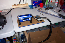
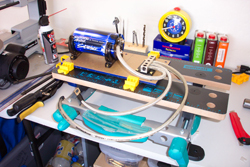
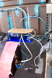
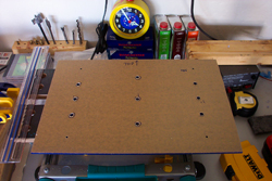
Testing the fit of the components on the plexiglass base.
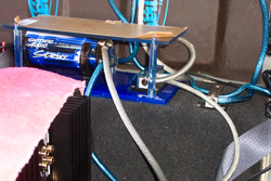
The distribution block is for the two grounds, one from the capacitor and the other from the Basslink amplifier.
The ground from the capacitor will be re-routed to the same side of the block. I need to find a vise to bend the connector to 90 degrees.
The translucent blue plexi supports that will hold the top piece of plexi. Center holes were drilled in the supports for the mounting screws. The holes are a hair smaller than the screws so the plexi doesn't crack. I'll fill about 1/4 of the hole with epoxy when I mount it so the screw will bond with the plexi.
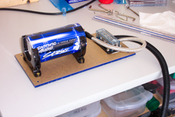
Top plexi on to make sure it clears the capacitor. All holes in both plexi plates are drilled to countersink the screws, both for attaching the supports and anchoring the bottom plate to the floor of the truck.
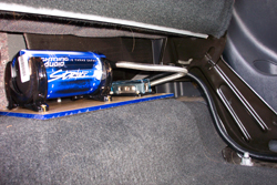
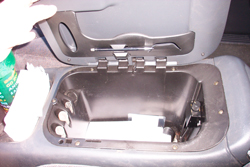
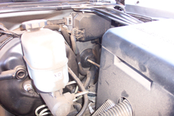
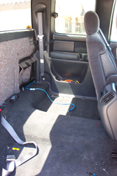
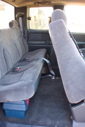
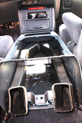
Making sure it fits under the seat. It was damn nice of GM to give me a shelf under there to mount this on.
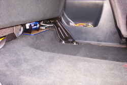
A better view of where it fits under the back seat of the truck.
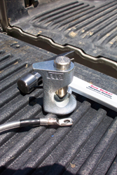
Crimping 4 guage wire is easy with the hammer style battery crimper from McMaster-Carr go buy one if you do this type of work.
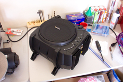
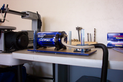
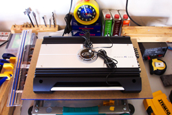
The Infinity BassLink. A 200 W Class D amp, 10" sub, and 10" passive radiator in a 15"x15" package.
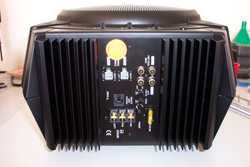
The available connections. My head unit has a subwoofer out so I won't have to tap into the speaker level connections, thank God :-)
It sits a bit more forward than I would like, but the hump just behind the front legs is metal raised up from the passenger compartment floor.
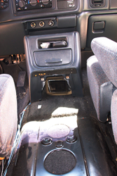
The remote bass adjust tucked into the center console.
It takes a 3/8" hole for the phone connection to be fed through.
The wire for the remote base adjust waiting for the install to complete. I'll probably make a small slit in the carpet to feed this to the back.
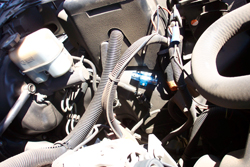
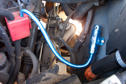
There isn't a lot of open space inside the engine compartment, especially within 18" of the battery. So I bolted the fuse holder onto the shroud for the wheel well.
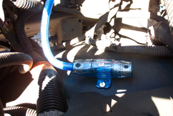
A nice view of the fuse holder with the initial wiring in place.
I'm using all Lightning Audio wiring and power distribution. This is one of their AGU fuse holders and is designed for 4 or 8 guage wire.
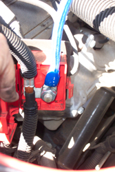
GM was also nice enough to give me this positive terminal about a foot from the battery - round crimp terminals are so much cheaper than new battery terminals :-)
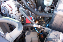
A view of the first wiring run that sorta shows where it sits in relation to the engine.
A better view of the first wiring run.
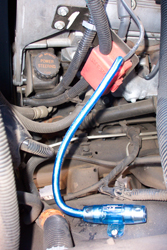
Another view of the first wiring run.
The last ground wire (for the BassLink) measured and attached to the distribution block.

Attaching the supports to the base plexi. The supports were tapped for the screws. I filled the holes about 1/2 way with Liquid Nails Perfect Glue 2 (a plexi bonder), screwed the supports onto the base, and clamped them.

A detailed view of the screw set into the hole that has now filled with the glue. The supports are screwed and glued :-)
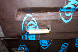
A likely place to punch through the firewall. There's a large bundle of cables already going through with an even larger rubber grommet. It's clear on the other side two. I cut a slit in the rubber and forced a small dowel through it.
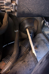
A better picture of the dowel through the firewall. I found the dowel on the inside and made sure that it was a good place from which to run the wire into the passenger compartment.
It's fuzzy, but you can see that I angled the end of the dowel and drilled a hole through it. Once the dowel was through the firewall, I strung some small wire through it and attached this wire to my power wire with tie wraps.
Pulling the smaller wire brought the power wire through. The two middle tie wraps do not hold the smaller wire - they are there to reinforce the last tie wrap if the smaller wire didn't let the tie wrap firmly hold.
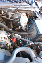
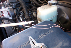
A picture of the final power wire run from battery attach point to entry through the firewall.
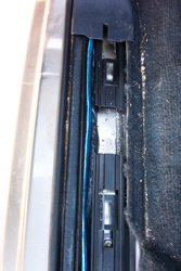
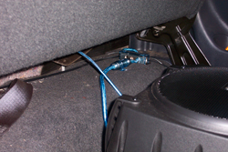
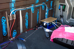
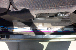
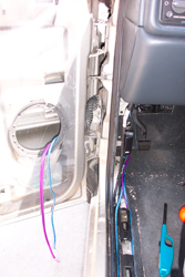
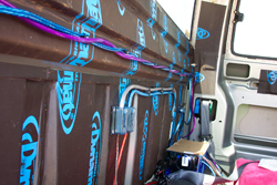
Inside the cab, I tucked the wire into the kick panel and ran it to the back under the rocker panel.
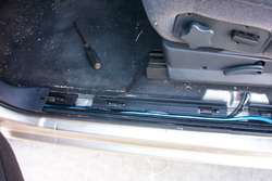
A pefect 4 gauge channel runs along the seat - thanx GM :-)
The wire under the back seat. It jumps out from behind the rear panel for the moment. For the final install, I'll have to pull the back seat and I'll tuck the wire behind the panel then.

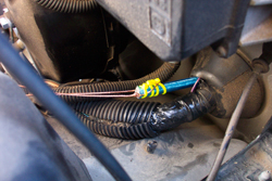
The Lightning Audio capacitor pass through installed on the end of the wire. This screws onto the cap and allows 2 4 gauge wires to connect on either side. Much neater than multiple ring terminals.
Attaching the top plexi panel. This gives an idea of the true color of the bottom plexi.
Lots of room with the back seat out :-) The wire is fully tucked under the side panel and the wire from the capacitor to the BassLink is in place.
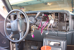
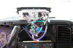
The Nakamichi head unit removed. The thick purple cables are speaker cables and will by-pass the system harness. These go to the Lightning Audio component speakers in the front doors.
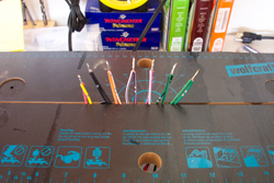
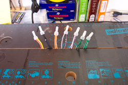
The JVC harness and the GM adapter harness furnished by Crutchfield wrapped and soldered. Soldering insures a good electrical connection.
Crimp-on insulators. These can also be used without solder for the connection if you're working in a tight spot.
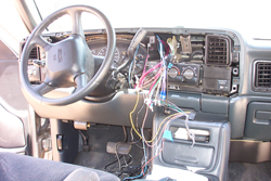
The harnesses installed. What a mess - good thing there's lots of room behind the dash.
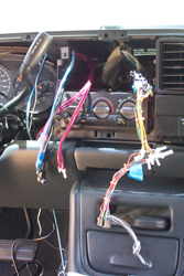
A bit of wire management and it looks much better. The wiring that will drop down out of the dash was routed to the left and dropped down beside the main instrument panel.
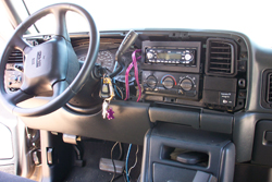
The JVC installed - now to take out the slack from the wiring dropping out of the dash.
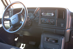
The head unit done :-)
I had to make some changes to the wiring - I wasn't originally planning multiple components in the back at this stage. Now I'll have the BassLink and the changer.
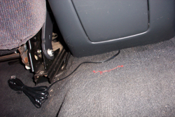
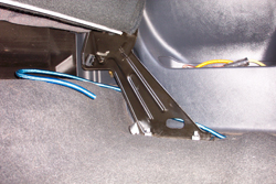
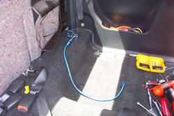
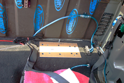
The wiring destined for the back of the truck was routed under the carpet beside the driver's seat mount...
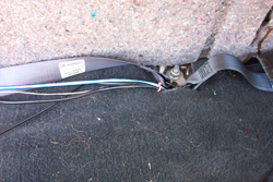
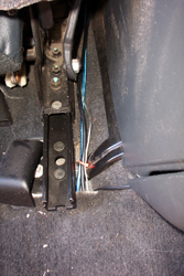
And brought back out at the back wall through a seatbelt anchor. Doing this required removing the driver's side rear side panel to be able to loosen the carpet from the floor. I used a wire fish first and then a lot of string.
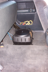
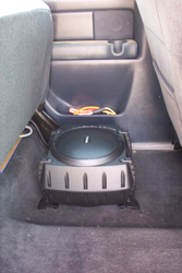
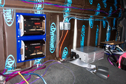
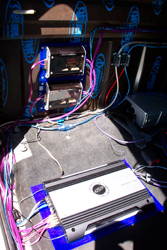
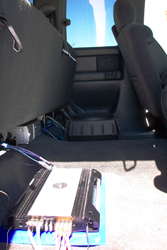
The BassLink installed.
Detail of the positive wiring. I think there's still gonna be room for the capacitor up there.
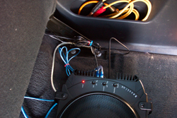
Quick and dirty wire management. When the capacitor and the changer are installed, I'll do this right.
A near-stealth installation, which was the goal.
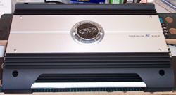
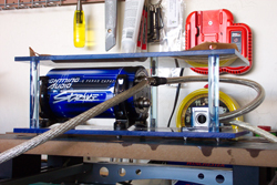
The new amplifier - Octane R 5.0.4, 50W x 4 channels - to drive the front and rear speakers.
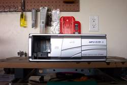
The JVC CH-X1500 CD/MP3 changer - 12 CD MP3's - Once I get 12 MP3's I won't have to change them for *years*.
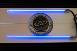
The neon tubes from Phoenix Gold that go into the "handles" of the amp to provide an ambient blue glow. They mostly match the blue glow behind the amp's logo.
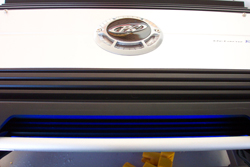
The tubes installed and fired up.
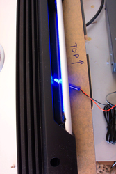
The Varad ILK blue LED's actually match the neon very closely.
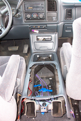
Starting to tear the truck apart (again) to run the wiring from the head unit to the amp and the power to the switch for the neons and LEDs. Notice the AC vents that come back through the center console. So *that's* why anything I put in the console gets cold on long trips :-)
Center console out. That A/C vent put out a lot of air without the vents through the console to direct it :-)
Back seat and trim panels out.
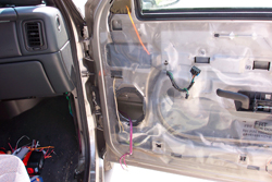
Passenger side third door trim panal removed.
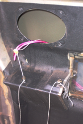
Old speakers out and existing speaker cables tied to keep them falling into the door. Later they will be used to pull the new speaker cables.
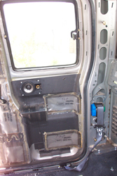
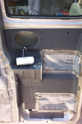
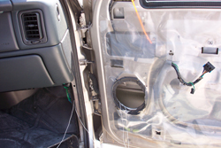
Dynamat added earlier when the old speakers were installed. Always label the plastic sheeting that covers the holes - it needs to be replaced and they are cut to fit each opening.
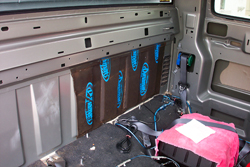
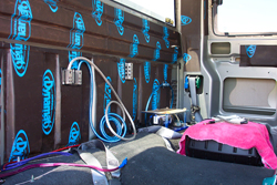
First sheet of Dynamat installed. I learned a *lot* putting in this first sheet. When you have a surface with large raised areas, adhere the mat to the raised area first. Then heat and adhere the mat to the lowered surfaces. This will keep the edges of the mat square and the next piece will match better.
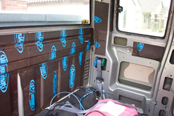
Dynamat done. Note to self - do this in the winter next time. Working with a heat gun in a passenger compartment in the summer gets *damn* hot :-(
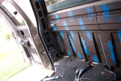
Yet another shot of the interior surfaces covered with Dynamat. Yes - I missed some small surfaces. Do I have buzz? Nope :-)
Slitting the mat lets you very neatly seal it around the various mouting fixtures that will inevitably be in your way.
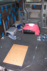
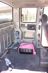
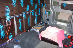
Placement test to make sure that components will fit where I intend and to measure/verify wire lengths.
Gonna have to relocate that fuse holder for the BassLink...
Yet another view of where the major components fit into the truck.
Removing the speaker wires and running the interconnects back to the Phoenix Gold amp.
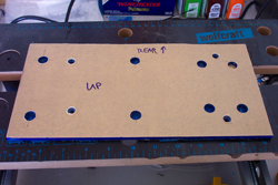
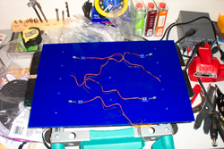
To mount the capacator plexi assembly, a sheet of plexi the size of the base will be screwed down onto the truck's floor. The cap assembly will then be glued to this sheet of plexi.
The smaller countersunk holes are for the mounting screws. They have to be countersunk so that the screwheads do not prevent the cap assembly from sitting flat on this sheet.
The larger holes are to allow the nuts from mouting the cap and distribution block to go through the mounting sheet. Again, the cap assembly's bottom sheet has to be flat against this one for this mount to work.
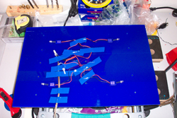
Stainless steel nylon insert lock washers were used to mount the capacator and distribution block to the plexi sheet. These nuts necessitated the larger holes in the previous image.
This looks like a good spot for the capacator assembly.
Seems to fit and lays flat against the mounting plate.
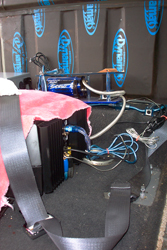
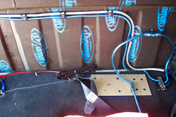
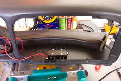
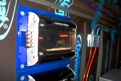
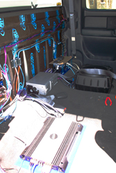
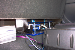
In the background of the image you see where the fuse holder for the BassLink ended up.
In the foreground are the distribution blocks for accessory power. The changer and lighting will be the first to feed from this.
Ground connection wired from distribution block, through the capacator, and dangling wire for the BassLink.
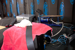
Power run to the accessory distribution blocks. I've run 8 guage cable to the center console where the 4 component switch will live.
Stinger cable mounts keep things tidy. The Lightning Audio capacator pass-through block sits on the mounting plate waiting for its cap.
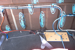
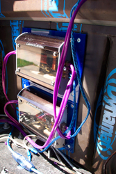
Another view of the main power wiring.
The BassLink's view of the primary power wiring.
Artsy view of the primary power wiring runs.
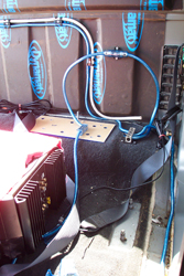
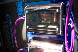
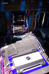
Capacator assembly installed and wired. To charge, I left the fuse out to open the connection to the battery and didn't connect the ground from the main ground distribution block. I then connected the charging circuit to the positive and ground leads that would go to the BassLink. When charged, I hooked it all up.
A better view of the main power distribution blocks.
A more detailed view of the wiring through the capacator.
New speaker cable for the rears. Lighting Audio 11 guage wiring. Tied off until the speakers are connected.
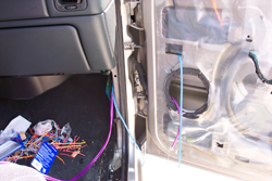
Old front speaker cabling. I attached string to these before I pulled them out. I then used the string to pull the new wiring.
Windex on the wiring helps it slide throught the rubber grommets and boots and keeps the gunk from sticking after the wire is pulled.
Old speaker wire pulled. I tied strings the the old wiring so that these strings could then be used to pull the new wiring into place.
New speaker wiring in place. More Lightning Audio 11 guage for the midrange driver and LA 16 guage for the tweeters.
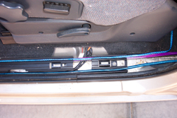
Speaker wiring from from the front through channels in the door sill panel back to the amp.
Excess wiring to be run to the crossovers.
Driver's side front speaker wiring.
On the driver's side, the speaker wiring shares the channel with the power wiring coming from the battery. The spacer was there - GM did a nice job giving me natural wiring features :-)
Driver's side front speaker wiring run up and across the back to where the crossovers will be.
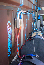
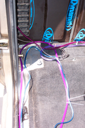
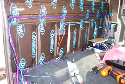
Artsy view of speaker and power wiring across back wall of passenger compartment.
The brains of a Pilot 4 component switch mounted to the inside of the wall of the center console.
Center console being put back into place. Interconnects from the head unit and power wiring from the back taped into place and hidden under the console.
View down through the center console. Why did I tape the wiring down? To keep it from being pinched by the mounting legs of the compartment of the center console.
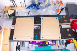
The plexi piece that the amp will attach to. I made a lot of mounting holes as I was initially going to mount it to the back wall of the truck. Didn't work out that way so I've got extra mounting holes that will be covered by the amp.
The amp hides all the mounting holes. The plexi will be screwed down the to floor and then the amp will be screwed down to the floor through the plexi. It wasn't planned, but no screws will end up visible.
Placing the lights that will make the plexi glow. There's a metal lip built into the floor of the passenger compartment under the back seat. Because of this, the plexi will have to float above the carpet. While this initially pissed me off, it allowed me to mount the lights under the plexi.
Wiring connected to the main lead and taped down. The Varad LEDs were glued in place.
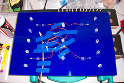
The plexi tubes that will space the plexi off the carpet to match the riser in the floor glued into place. They align with the screw holes so even if the glue doesn't hold, the spaces will always be in place.
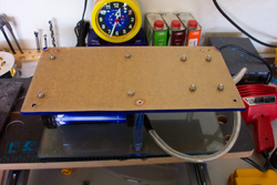
The crossovers for the front speakers have no mounting holes. So they will be glue do pieces of plexi that will be then be screwed to the back wall of the passenger compartment.
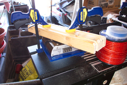
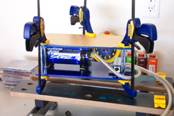
Crossover epoxied to the plexi sheet. I used the 2x4 to equalize the pressure of the clamps and to prevent cracking the plexi covers of the crossovers themselves.
The crossovers mounted to the rear wall of the passenger compartment.
They're pretty cool looking crossovers. Too bad I want this install to be stealth and they'll be behind the back seat.
Speaker and amp wiring to the crossovers. It's messy because the amp and speaker connections of the crossovers are on the "wrong" sides.
Detailed shot of a crossover and the wiring. The metal screw replaced the correct tap - it stripped on the way out.
Crossover and amp in place.
Less glary shot of the crossovers and amp installed.
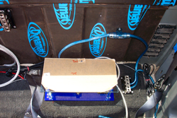
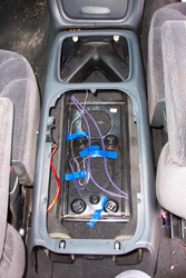
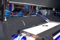
Everything in place. Just need to peel the protective paper from the capacator assembly's top plexi and put the back seat in.
Back seat is in - this install is done. Now to tune the amp and BassLink to each other.
The amp's fuse sits on the shelf right above the amp. The jack used to be there but is now mounted in the bed tool box.
Capacator assembly nestled under the back seat.